Modelling Transient DRS Activation in CFD
Introduction
The current generation of Formula One (2011 to present) uses a Drag Reduction System (DRS) to reduce the drag force resisting the cars motion in certain conditions. The system was introduced to improve the overtaking opportunities during races. The current DRS system features a mechanism to rotate the rear wing flap to an open position, reducing both the downforce and drag, giving the car a boost in speed. In a straight ahead condition, there is no requirement for the large amounts of downforce being produced, which acts only to slow the car down.
Of course, the easiest way to investigate the effect of DRS on performance is to simulate two steady-state conditions, with the flap open and closed. This allows direct comparisons of downforce and drag in both conditions, giving an indication of how important the system is. This is likely the only approach of interest for the current generation of cars, since the time spent opening and closing the flap is minimal and thus the transient effects can be neglected. However, where would be the fun in that?
The aim of this study is to investigate the capabilities available within the open source CFD software, OpenFOAM for this type of modelling. The most common approaches for modelling mesh (component) motion within OpenFOAM are the sliding mesh and overset mesh approach. Both of these methods are inherently expensive, due to the extra computation required to perform the transformation on the mesh, correct for the motion and perform an interpolation between mesh regions. In addition, this is a transient problem.
Geometry
The geometry selected is the rear wing profile from the PERRINN 2017 car. The profile features a typical rear wing configuration, with a main plane and flap. The flap also features a lip. This generation of F1 car features the DRS described earlier, in which the flap is rotated to an open position to offload the car in straight ahead, overtaking conditions.
Ideally, a 3D simulation would be performed, with the rest of the car present. This is because the aerodynamics of an F1 car is massively 3-Dimensional and coupled; each component works together with the rest of the car. The rear wing is supported by the beam wing and diffuser to remain attached, while the beam wing and diffuser are also supported by the rear wing. Modelling a component in isolation is not advised, since the onset freestream conditions will not be appropriate. This is especially true for components at the rear of the car.
However, with limited resources and a plan to only investigate methodologies, it's appropriate to start with the basics and work upwards. For this reason this study only considers the rear wing elements, in a 2D simulation.
Methodology
CFD Software of choice: OpenFOAM.
OpenFOAM is a powerful open-source CFD platform, completely free to use.
Since the flap must be rotated, a solver which supports transient flow with moving mesh must be selected (overPimpleDyMFoam). It is not possible to use a sliding mesh approach, since the flap overlaps the mainplane, hence an overset mesh approach is employed.
A moving overset mesh approach is typically made up of two (or more!) components, the stationary background mesh, and the moving overset mesh(s).


The motion profile of the flap must be defined. An arbitrary axis of rotation somewhere towards the trailing edge was selected. The desired angle of rotation required to orient the flap into the DRS open position was determined. The time to open/close the flap is unknown, so 0.1s was chosen. With this information specified in the dynamicMeshDict, the movement of the overset region (the flap) is defined.

Results
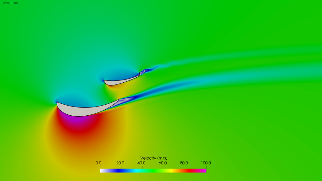
It's clear to see there is a massive separation off the flap in the DRS closed position. This is clearly not the expected behavior of the wing when on the car, but occurs because the operating conditions of the wing in isolation are far from what they are on the car. Without the support of the beamwing and diffuser, the wing stalls.
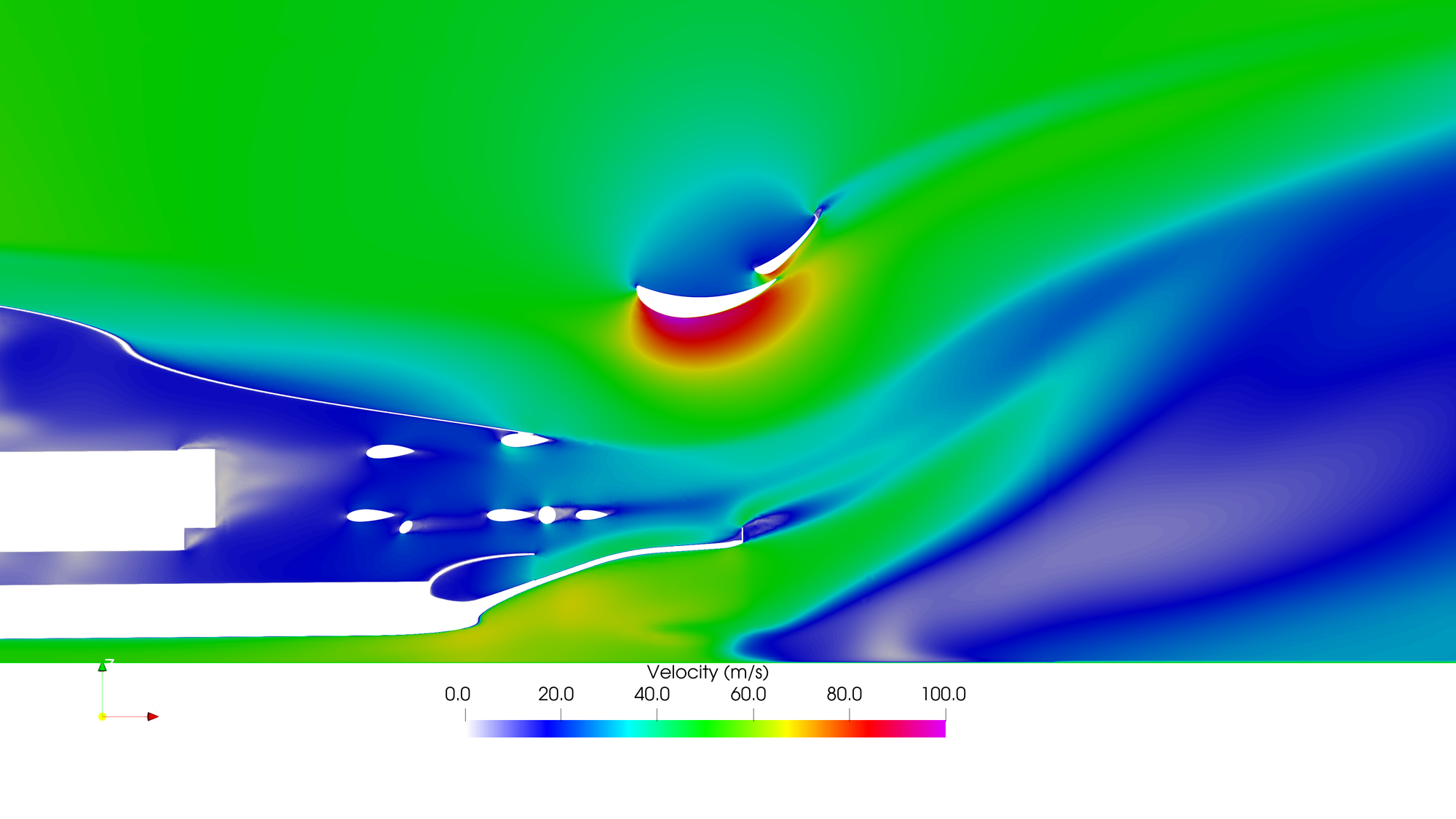
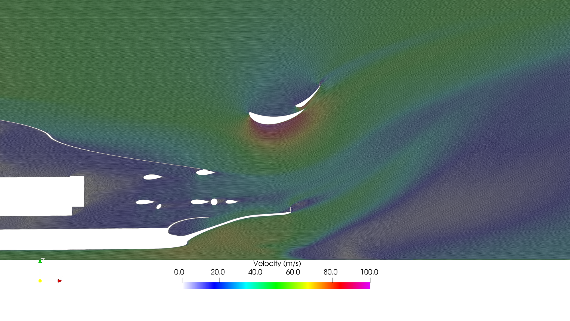
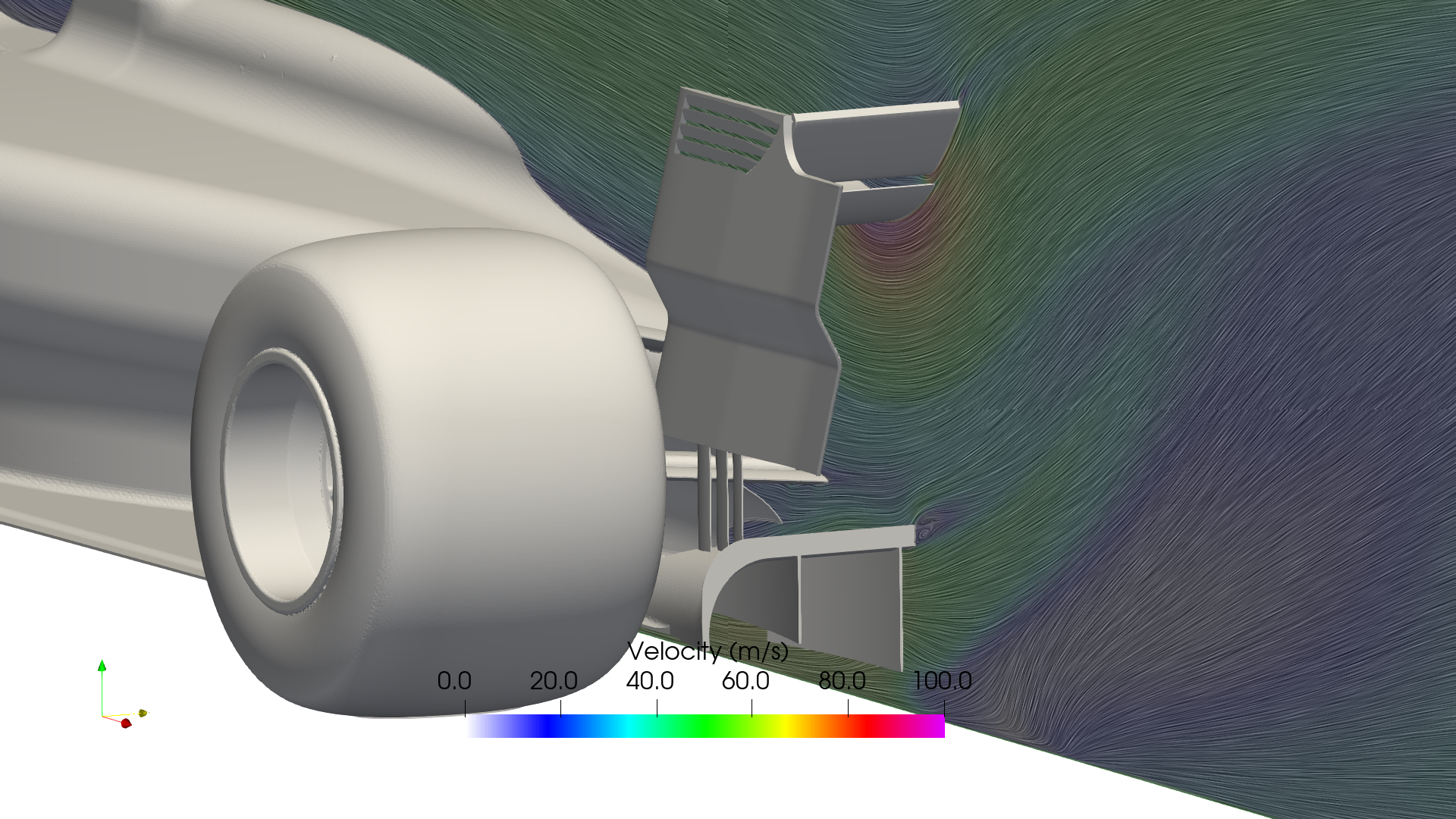
Here are some images which show the expected velocity profile when the rest of the car is present, including the diffuser, supporting the rear wing:


