Modelling Road Vehicle Self-Soiling Using a Lagrangian Particle Tracking Approach
Introduction
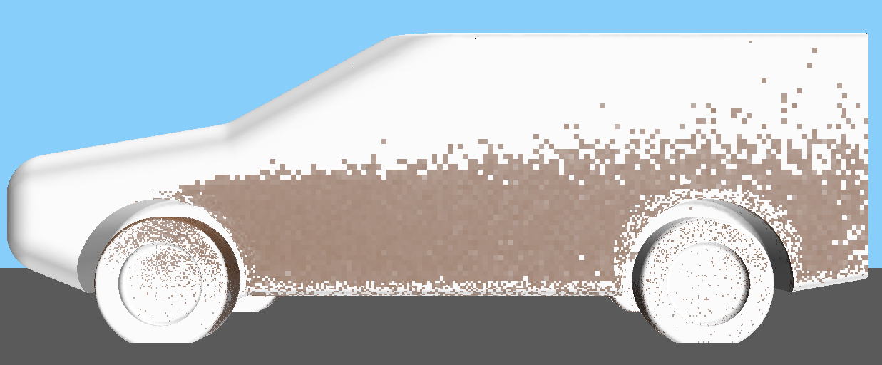
The term "self-soiling" describes the process in which a road vehicle is contaminated via 'dirty' water thrown up by its own tyres. Other than affecting the vehicle aesthetics, soiling is becoming more of a safety concern as vehicles become more reliant on Advanced driver-assistance systems (ADAS). The function of ADAS sensors, particularly cameras, can be impaired by surface contamination. Thus, prevention of contamination leads to improves reliability for ADAS systems.

The aim of this study was to define a CFD methodology that enabled rapid assessment of soiling patterns on vehicles.
Geometry
Both time and compute constraints on this project meant sourcing a simple geometry, which is still representative of a road car. A generic SUV geometry provided by Loughborough University was selected. The simple nature of the geometry allowed for less time to be spent on pre-processing and mesh generation.
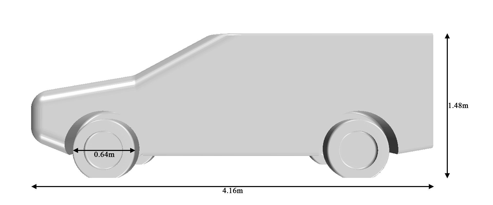
An isolated rotating tyre was also modeled, to validate spray patterns against previous experimental and numerical research. The first step was to experiment with the particle physics on an isolated tyre, then migrate the process to the full car.
Particle Physics
The trajectory of a particle is derived from integration of its acceleration, resulting from the forces acting upon it. The key forces to consider in this instance are drag and gravity. Other forces such as buoyancy and pressure gradient forces can be ignored, due to the size of the particles, and huge difference in density between the two phases.
The particles are treated as spheres and therefore follow spherical drag law. They are uncoupled to the flow, since their size and quantity have limited effect on the continuous phase (air). Particles are assumed to be water droplets, therefore have a density of 997 kg/m3.
Since the particles are solved on a 'frozen' steady flow field, a turbulent dispersion model is needed. This is to represent the unsteady flow characteristics and prevent particles released from the same point from following the same path. The velocity used to calculate the drag force is therefore composed of two components, the Reynold's averaged velocity calculated during the continous phase RANS solve (𝒗̅) and a pseudorandom velocity perturbation, proportional to the local turbulent kinetic energy (𝒗′).
𝒗 = 𝒗̅ + 𝒗′
Since the particles are solved using Newtonian mechanics, it is relatively straight forward to estimate their trajectory empirically. A quick MATLAB script was developed to calculate particle trajectories when released from a rotating tyre into a 22.2ms-1 flow. The resulting trajectories are presented below.
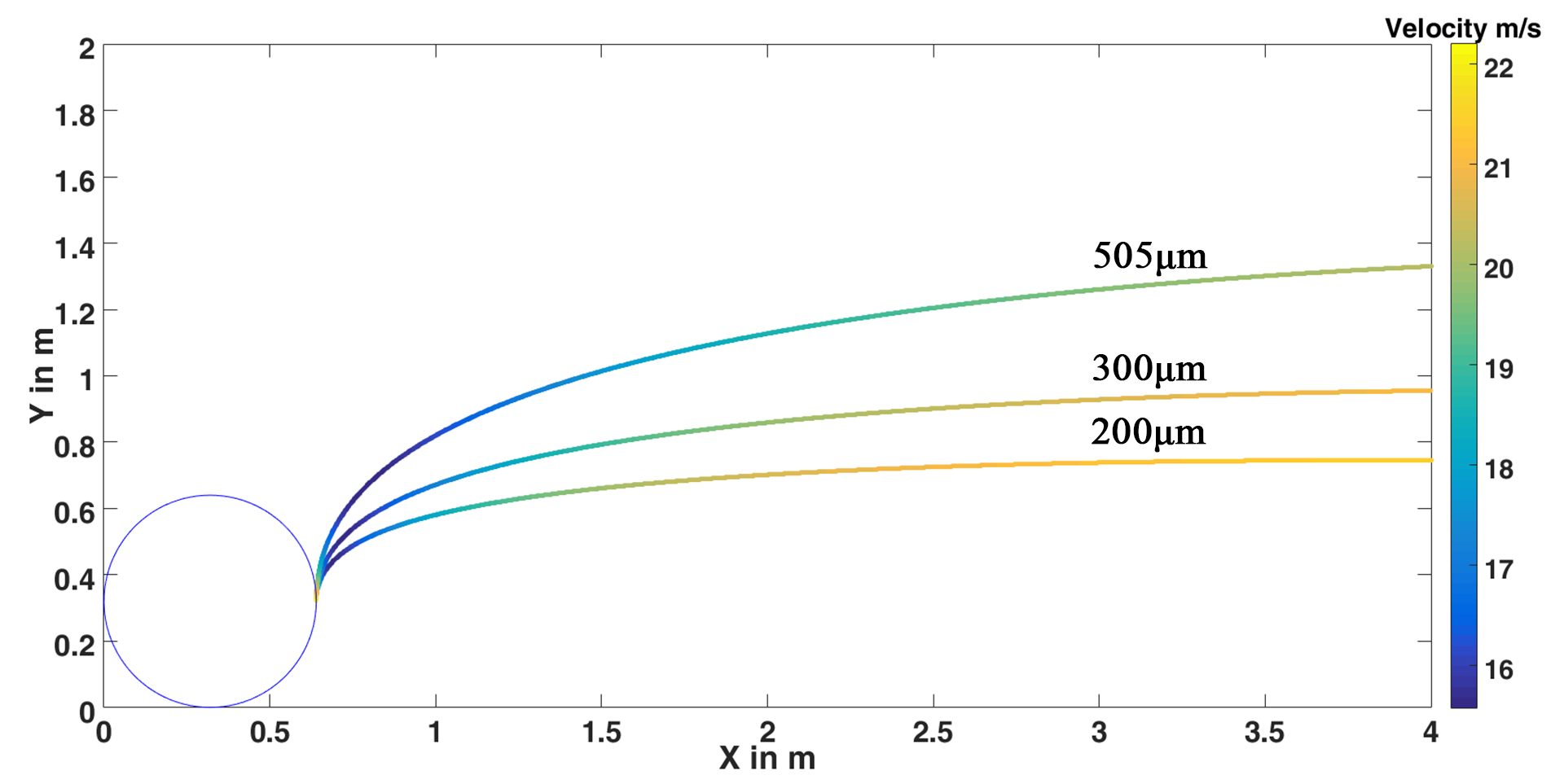
This plot indicates clearly the relationship between particle diameter and sensitivity to the flow. Particle inertia is proportional to volume, whereas aerodynamic forces are proportional to the projected area. This means inertia increases with D3 but aerodynamic forces increase with D2.
CFD Results
Isolated wheel
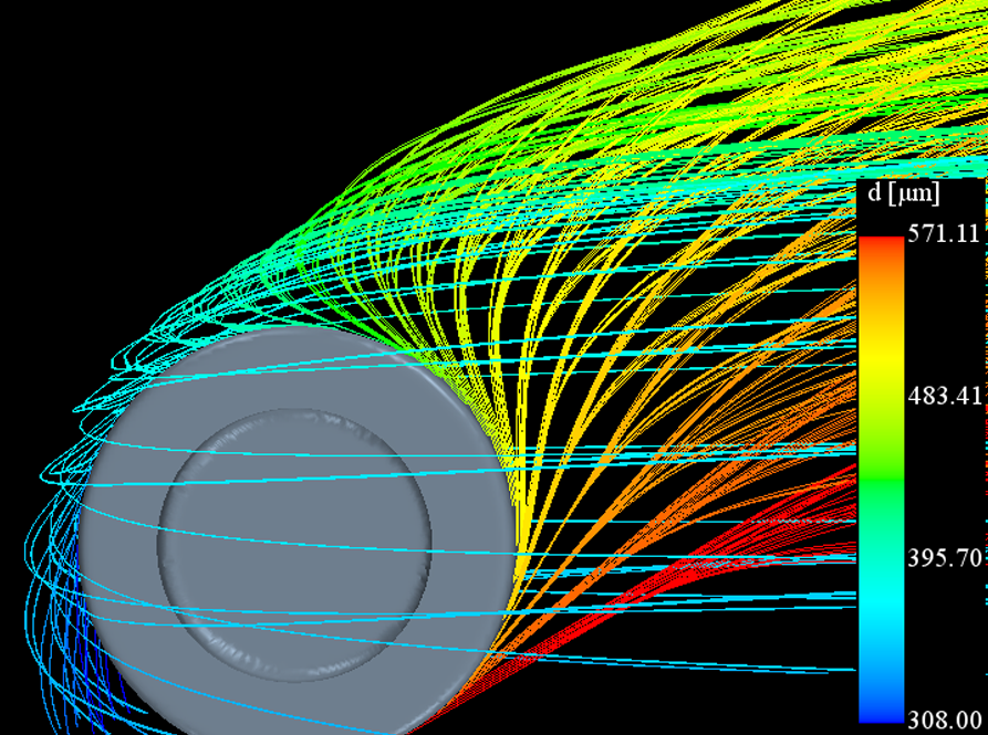
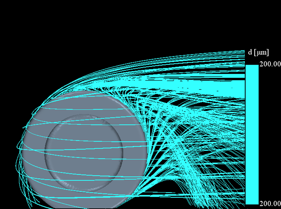
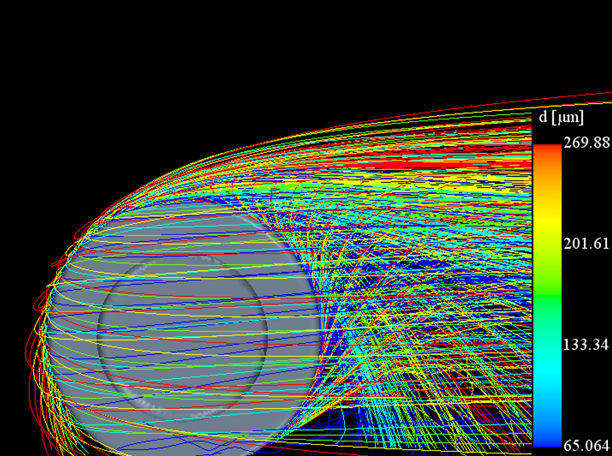
Particles were injected from raked injectors distributed around the tyre. These injection rakes were separated by 10 degree intervals, from 30 degrees to 270 degrees. The injection velocity vector was equal in magnitude and direction to the local tyre surface velocity. This methodology is outlined by A. P. Gaylard in a 2011 study [1]
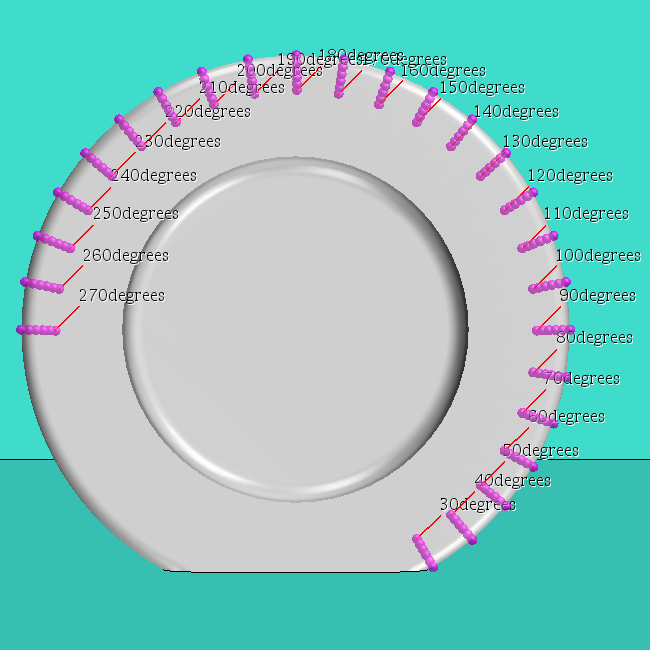
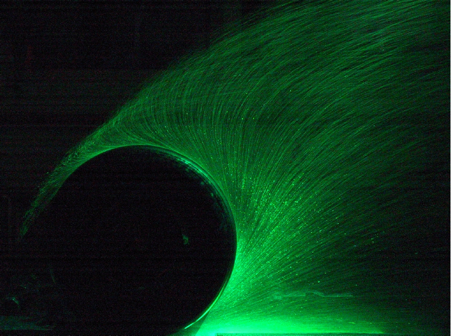
Three spray size distributions were tested in CFD. A free-stream velocity of 22.2ms-1 was used to match experimental data. Tyre rotation was modeled using a moving wall boundary condition. The images below present qualitative comparisons of each particle size distribution to experimental data obtained by T. Kuthada and S. Cyr in 2006 [2].
Full Car
tbc...
References
[1] A. P. Gaylard and B. Duncan, “Simulation of Rear Glass and Body Side Vehicle Soiling by Road Sprays,” in SAE International Journal of Passenger Cars, 2011.
[2] T. Kuthada and S. Cyr, “Approaches to Vehicle Soiling,” 4th FKFS conference on profress in vehicle aerodynamics and thermal management: numerical methods, pp. 111-123, 2006.
